From Theory to Practicality – Comb Filtering November 22, 2008
Posted by ConnorSmith in : Acoustics, Digital Audio Workstations , trackbackWhat is comb filtering? What does comb filtering do to the audio? What causes comb filtering?
^^These are all things that people involved in audio (from beginners to professionals) should know. This article will discuss comb filtering from theory to practicality. (Including a preview of a MAX program I’m working on that will do all the plotting and calculations for you…)
So first off: What is comb filtering and what causes it?
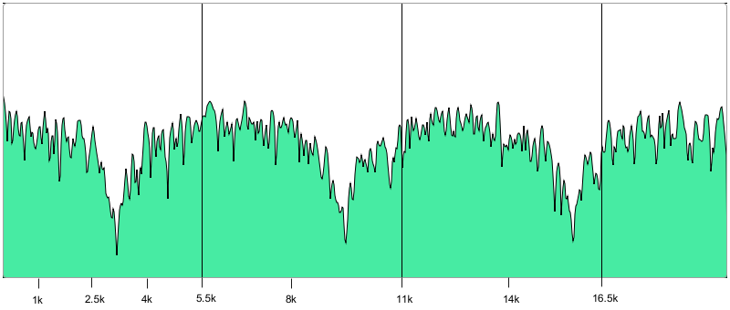
Comb filtering is a type of filtering that occurs when a signal is combined with a delayed copy of itself (or, if not the exact signal, something with similar frequency content). The interference now caused by the difference in phase of the waveforms causes very deep notches to be taken out of the spectrum at regular intervals. In between those notches, wide boosts of +6 dB occur. In this picture, I have taken a L and R channel of white noise, delayed the R channel by a number of samples, and combined them. This is a look at a linear spectrogram (not logarithmic, for this picture, it will look better):
Let’s compare this to what white noise normally looks like on a spectrogram:
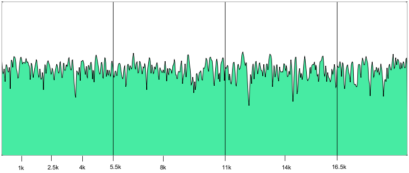
Ouch, right? So by the looks of it, we have some seriously negative EQ happening to the delayed and summed white noise. (Its not necessary for the scope of this article, but) If you do the math, you will find out that the first “notch” taken out is at 3150 Hz, and the next “legs” of the comb filter occur every 6300 Hz (so at 9450 and 15750). In between, we have some wide gain applied.
As a the delayed signal moves farther and farther away from the non-delayed track, the number of filtered bands goes up. So, up there^^ we were delaying the signal in the R channel by 7 samples. What happens if we delay it by 17 samples instead? This is what we get:
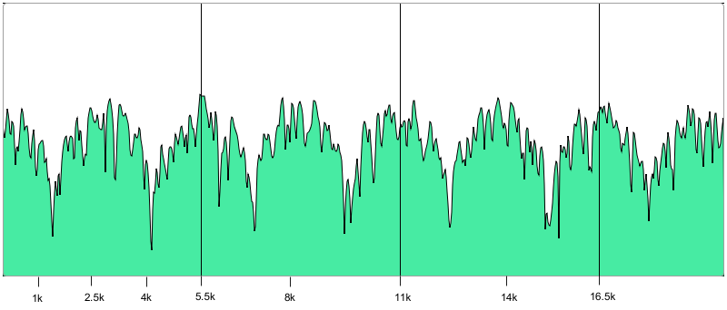
Ouch more, right? Now we have 7 notches taken out, starting at around 1.3K and occurring every 2.6K (again with gain in between).
So, before we move onto “Why this is relevant to recording?”, make sure its clear that this filtering is happening because a signal is present twice, and one instance of it is delayed; when the delayed combines with the original, filtering occurs (based on the delay time).
Probably one of the prime examples of a “COMB FILTERING DANGER ZONE” is when recording a drum kit. Here you have a slew of mics to place. While ideally each mic would only pick up the drum it was aimed at, inevitably there will be bleed from mic to mic.
A great example of where to watch for comb filtering is on the snare drum. Very often, engineers will place 2 mics on the snare drum (top and bottom mics). So now we have two relatively similarly sounding tracks that are going to be combined.
Uh oh – If there is a delay present between these two copies of the signal, that we are creating a textbook definition of comb filtering. Why would there be a delay? One common way this would happen is if the mics are at different distances from the drum. If it takes longer for the sound to get to one mic, that mic will be delayed in relation to the other. It may be prudent to make sure that the mics are equidistant from the drum (as to avoid filtering). I’m not done with this Max/MSP program yet, but here is a screen shot from a program I am making. Right now, you can choose the source material and then delay a channel by an amount of samples (and it does the calculations for converting that to milliseconds and inches). Inches translates to how many inches your mics’ diaphragms would have to be “off” to cause this filtering (based on the speed of sound). I’m hoping (once completed) that this program will be a good reference. So, in this picture, notice that I am delaying 7 samples (notice the filtering) and also notice the number under “Inches”. A difference of a few inches can make a big difference. (Click to enlarge)
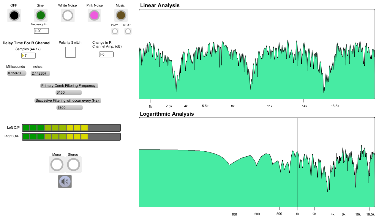
(Currently I’m working on getting MAX to plot the theoretical comb filtering function, rather than just tell you the primary frequency and interval.)
Despite all this, I wouldn’t get too neurotic about measuring the distance of every mic you place. For starters, just use your ears when bringing up levels in the control room. If things sound “phasey” or weird, then you know something is wrong. Often this can be fixed just by flipping the polarity inverse switch (often mislabeled the “Phase” switch) on the preamp of one of the mics. Sometimes comb filtering can even be a good thing…
Most importantly – be aware of comb filtering (and its causes) and always use your ears within this context. When pulling up mics in the control room, listen for these cancellations.
I’m hoping to have this program done soon, and with some adaption, I would like to make it available for TheStudioFiles.com. Its even good as ear training, as you can load up sound files and delay them to practice listening for filtering.
More on this as we begin to delve into drum mic’ing techniques…
C
The Studio Files
Comments»
Can you explain the phase/polarity issue addressed above, and why it’s “mislabeled”. Thanks.
This article should help –
http://thestudiofiles.com/?p=127
Most important, remember that polarity is just a switching of the + and – voltages (flipping the signal upside down), where phase is about a time relationship.
[...] [...]